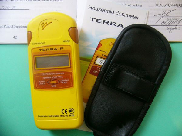
The readings of
radiation detector depend not only on the radiation intensity, but also on the individual characteristics of the
radiation detector (type of counter, geometry of measurements, etc.). To switch from the measured intensity (in pulses / min or scale divisions) to the true intensity (more precisely, to the dose) of γ-radiation (in μR / h), it is necessary to establish the nature of the relationship between them, called a reference characteristic or a reference graph. The reference graph allows one to take into account both the sensitivity of the radiation detector and the nonlinearity of the dependence of the readings on the radiation intensity caused by the counting circuit of the pulses.
To obtain and refine the reference schedule, the
radiation detector are standardized prior to the start of work and systematically during searches (2-3 times a month). Re-standardization is also mandatory after the repair of radiation detector or when changes in its sensitivity are established during daily checks using a working standard.
For standardization of field radiation detector , a 10 by 15 m area with a minimum activity of rocks and far from structures and objects that can interfere due to scattering of radiation from the reference source is selected. At a distance of 6-10 m from each other, two pillars approximately 2 m high are installed, between which a cable or wire is stretched. A radiation detector is installed in the upper part of one of the pillars. The axis of the radiation detector should be on a vertical plane passing through the cable, 8-10 cm below the latter. A reference radium source of known activity is suspended from a cable. Its center is located at the same height as the center of the detector. By installing the source at different distances from the detector, different radiation intensities are created. In this case, the radiation intensity (in μR / h) is calculated by the formula:
Iγet = 840a / r2
where: a is the activity of the radium source in mCi; r is the distance between the source and the detector, m; 840 μR / h - radiation dose from 1 mg of radium at a distance of 1 m.
Based on the results of measurements at various values of Iγref, a reference graph is built. By extrapolating this graph to zero readings of the device, the background intensity Iph at the calibration point is counted on the abscissa axis, and by shifting the scale on the abscissa axis by the value Iph, the final scale Iγ of the reference graph is obtained (lower scale).
For spectrometric equipment, in addition, the energy scale is standardized, i.e., the relationship between the radiation energy and the pulse amplitude at the input of the discriminators (or otherwise the channel number of the amplitude analyzer) is determined. To study this dependence, one usually studies the spectrum from several sources with different radiation energies and builds a graph of the relationship between the discrimination level in volts (channel number) and the radiation energy. To standardize the energy scale, sources are used from Cs137 (radiation energy 0.662 MeV), Co60 (radiation energy 1.17 and 1.33 MeV).


